Shipyard Transporter Ultimate Guide - Learn Technical Specs (Heavy Duty Industrial Transporter)
Resources | by
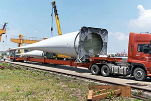
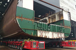
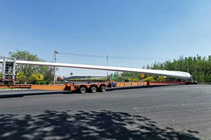
A shipyard transporter is a heavy transporter and a bulky equipment hauler normally used in shipyards but could also be used elsewhere where the load demands is similar to that found in shipyards.
As defined by the name, a shipyard transporter / shipbuilding industrial transporter is used in the transportation of ship / steel sections from the builder point to the assembly point.
This type of transporter uses a hydraulic suspension and steering to attain loading, movement and steering capabilities. Each of the wheels has its own steering unit.
As a result, the shipyard trailer can attain 8 directions of movement with a possibility of turning 360 degrees from the center point taken as its point of origin.
1. Introduce of the Shipyard Transporter
1.1 Use of the Shipyard Transporter
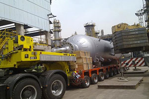
The shipyard transporter has various industrial applications and uses. It is commonly used in the transportation of ships and ship sections, heavy industrial equipment and vehicles.
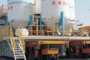
Industrial facilities such as shipyards, factories and power plants usually use large and delicate equipment needed for their operations.
The handling and movement of such equipment within the premises and off their premises for testing and/or for installation in different locations requires a lot of care and high transportation capabilities.
Without transporters of the magnitude of a shipyard transporter, it would become almost difficult to make this happen. Traditional lifting tools and equipment cannot suffice.
The development and building of the shipyard transporter is therefore needed for providing a solution to the limitations realized with conventional cranes.
The gantry crane is for instance, used on the handling of heavy tools and machinery among other heavy objects.
However, its capabilities can’t match the lifting needs for ship sections and the fully assembled ships on a yard. Such equipment as fork lifts and gantry cranes are not able to lift up large equipment that are high, long and bulky.
A lot of maneuverability is required when lifting this heavy equipment and that is one of the solutions that the shipyard transporter offers.
The lifting equipment that comes close in this category is the overhead crane system but is commonly used in indoor operations or in a certain fixed point.
Ideally, they can carry the ship sections built in the workshop as they move them from one point to another but not able to transport them outside the building or beyond that designated point.
This is so because the overhead crane is normally mounted to two opposite sides of the building walls.
With the overhead crane unit, the load is carried by the hoist attached on a trolley as it moves along the beams. In this kind of arrangement, it is not possible to move a section of the work or equipment from one yard to the next.
This is because the track system in this lifting equipment extends to certain points that cannot be exceeded.
Looking at the challenges posed by conventional lifting equipment in the handling of heavy objects, the shipyard hauler is therefore a perfect solution to this.
While this equipment need a lot of space to operate, the shipyard transporter is not confined to one place.
1.2 Technical Specification
A shipyard transport is meant to take up very heavy loads to the tune of over 80 tons. This kind of ability is made possible through the use of many track-axle assemblies as is the case with a shipyard transporter.
All these track-axle configurations have dedicated self-loading suspensions on each one of them and an on-center axle ability to rotate.
Every track-axle assembly in this shipyard hauler has a hydraulic piston and a cylinder housing where the first and the second track units get connected on opposite ends of the axle’s frame.
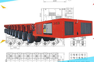
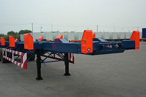
1.3 Brief Structure of the Transporter
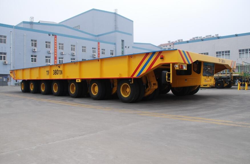
The shipyard transporter presents are a multi-wheeled hauling vehicle that has abilities of lifting, loading and moving very heavy equipment.
It is adapted to do this over rugged terrain without any torque loading and safely deliver the cargo to its designated point.
The structure comprises a modular wheel unit having a low profile that has attachments used for equalizing and balancing the loading weight exerted on each of the installed wheel units.
shipyard transporter brief drawing
1.4 Running conditions
The shipyard transporter will operate maximally in conditions with ambient temperature within the -10 C~ 45 C range, a relative humidity of ≤95%, in salt mist conditions. It is commonly used for outdoor operations.
2. Structure and Performance
The shipyard transporter manufactured by our Company is a special purpose vehicle which is equipped with a hydraulically operated lifting and lowering facility and is suitable for transporting heavy loads.
This transporter is composed of a framework platform, drive axle, slave axle, engine power unit, hydraulic lifting system, hydraulic driving system, hydraulic turning system, hydraulic oil supply unit, braking system, major-minor cabs, micro-electric control system and vehicle-electric system.
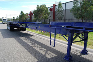
2.1 Frame Structure and Platform Covers
The platform is a high rigidity structure with good bending resistance and high flexibility that can hardly be deformed even when under impact load.
With the sufficient surplus in strength and stiffness, the vehicle can equalize the loading on it. The load allocation and the caution labels are marked distinctly on the frame with lifting lugs well-installed on both sides of the body.
All platform covers are a easily removable type of sash armor plate. The thickness of the armor plate is usually over 5mm in order to provide the desired strength.
2.2 Turning Wheel Carrier
The Turning Wheel Carrier is composed of a pivot arm, swivel frame, slewing bearing, bearing bridge or driving bridge and a lifting cylinder. The turning wheel carrier is mounted on the slewing bearing of the vehicle frame.
When on the transverse bumpy road, the swing of axle supplies compensation.
When on the longitudinal bumpy road, the group of hydraulic lifting cylinder supplies longitudinal compensation. When on the slope, it can adjust the level through the lifting cylinder.
2.3 Electro-Multi-Mode Steering System
With electric control-hydraulic turning, the shipyard transporter manufactured by our Company steering in multi-models includes straight going, conventional turning, and oblique marching, tilting head or tail and circling from any given radius.
In addition, user can add other turning models to meet the needs. There are 6 standard turning models as follows: a) Conventional Driving; b) Automobile Driving; c) Oblique Driving; d) 90°Angular Driving; e) Circle Driving; and f) Crab Driving.
Multi Mode Steering
In the in-situ circle driving, the vehicle circles around its symmetry center. In the conventional driving, all wheel carriers move like this:
All axial center lines intersect a point o, which can be in, out or on the side of vehicle. The minimum of involution radius is permitted to be zero.
In the automobile driving, the radial axle is on the back shaft that is defined by the position of cab. In oblique driving, the angle is in the range of -90°~90° can be selected.
Steering is operated through rotating steer wheel connected to an encoder. Each wheel carrier has an angular sensor, which sends the position signal to the controller.
Then the controller compares the actual position with the set value. Proportional valves control each turning cylinder that is connected to each separate wheel carrier through a connecting rod.
If steering deviation is over 6°, the instrument panel in the cab will flicker and the steering wheel will be locked.
2.4 Braking System
The shipyard transporter has compressed air braking system with the following smaller systems and parts:
- Braking cylinder: Working through the aggregate unit consisted of spring and diaphragm braking air cylinder. If a compressor breakdown should occur, the system brakes through the spring.
- Pedal brake: The compressed air from the gas reservoir enters the diaphragm cylinder to make braking.
- Parking brake: With forcing the spring, parking brake can be availed (even if the pipeline has a breakdown).
- Brake drum: The steel brake drum is enclosed to prevent dust from entering the braking system.
With the service and parking braking, the loaded vehicle will be anti-slipping in case of the 8% slope reliable. The brake valve and the relay valve are applied in the process of braking.
2.5 Driver’s Cabin
There are two separate cabins, which are design in accordance with the standard, on each end of the vehicle.
It mainly consists of a controller, liquid crystal display, electric system, instrument and an air conditioner.
Except the liquid crystal display and the hour meter in the major cab, the 4 pressure gauges in the slave cab, both drivers’ cabins have same functions. In addition, the cabs function as follows:
- Sufficient space for single driver. The chair can be adjusted longitudinally, backrest also can be adjusted.
- Screen wipers and flushers. When the door is adversely opened, and is equipped with removable glass, all the glass is safe and the driver can have good view in three directions.
- With instruments in distinct arrangement and soft illuminations, the vehicle can be operated and monitored easily
- Slave-cab configures pressure instrument to monitor four groups of lifting cylinders on the dashboard with cooler and water heater and fire extinguishers in each cab.
- Each cab is equipped with two back mirrors, a shadow shield, an ash tray and a cloth hood. The major cab has multi-function English display instrument. The fluid crystal display: including the gravity center, the load weight, bug diagnosis, load deviation and alarm, overload and self-locking and turning model.
2.6 Electric Configuration
The entire transporters voltage is 24V, with two 200AH batteries. The electric-control monitor instrument with the cabins not only has common operation, but also has following functions:
- Instrument indication: oil press and water temperature of engine
- Alarm lamps: the plugging of the high-pressure filter, ingress or return oil filter – the lowest level of oil
- Functions as a lighting point for head light, dipped headlight, rear blinker, backup light, warning light, parking lights.
The system is equipped with the control unit box and the entire control component are in the control box.
The marks of the line number (terminal no.) on the vehicle should in accordance with drawings, and all kinds of marks be firm and reliable.
All the components of the vehicle should be available, and in accordance with the drawings.
The configurations of the electric system such as special controller for the engineering truck, LCD, angular displacement sensor, pressure sensors are imported, which satisfy the standard of IP65.
Common electric component and cable adopt first-rate joint venture and war industry product. The electric-control box and electric component satisfy the standard of IP 55.
2.7 Hydraulic Lifting System
The shipyard transporter has an electro-hydraulic lifting system. The total stoke length of the platform is 600mm.
Generally, when the platform is lifted by 300mm, the stroke is enough to compensate the axial load. The lifting cylinder is installed at the turning wheel carrier.
With the moment suspended freely, the cylinder can be kept off damage. By manipulating the switch, the platform can rise and fall off horizontally. In addition, there are 4 manual hydraulic valves in order to descent the platform in the emergency.
2.8 Over Load Protection
The hydraulic lifting system and steering system have an overflow valve that is independent to ensure the system pressure will not overload, and protects steering cylinder, lifting cylinder, wheel carrier and steering structure as well.
2.9 Drive System
The hydraulic drive system of the vehicle, adopting Rexroth’s sophisticated technology, ensures the engine output can match with the actual power under various operating modes.
Under this condition, the engine and driving parts can prevent the overloading efficiently in case of engine shut-off. In order to avoid shutdown, the rotation speed of the diesel engine and the pace of the vehicle are controlled by the pedal accelerator.
2.10 Hydraulic Oil Cooler
The shipyard transporter adopts an independent cooling system. Hydraulic oil will be elicited from the tank by an oil pump to the radiator.
After radiating, a part of the hydraulic oil will flush the driving pump and turning pump and the other part of the hydraulic oil will return to the tank directly.
Independent radiating system ensures that the hydraulic system will not over-heat after long hours in the permitted running condition.
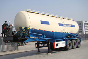
2.11 Hydraulic Tank
The hydraulic tank is made of stainless steel. There are first-rate filters installed on the suction and return pipe, which cleanse the hydraulic oil.
They can reduce the impurities to the lowest effectively, and therefore increase the reliability of operation and lifespan.
The combined suction filter is installed on the retaining valve, so you only need to remove the element when you repair the transporter. You however, do not need to let out the hydraulic oil.
2.12 Direction Selector
Direction selector steering control has five ranges: the middle range is the neutral position.
Drive and reverse’s second gear can change from first range directly. From neutral position to first range, it is needed to release the locks with.
2.13 Safe characteristic of pipe break
Our Company adopts dual-circuit protection valve to protect the lifting system. If the pipe breaks, the lowering of pressure bring flow pulse immediately, and the explosion proof valve on the breaking pipe will to be shut.
The other pipe continues to join the cylinder which belongs to the same group. The transporter also can accomplish the task because of the load compensation function.
2.14 Surface Machining
After shot-cleaning, the surface of the steel structure reaches SA2.5 grade. The thickness of the application and paint film must be up to the national standard (more than 150μm).
The paint chooses the well-known brand. And the standard top-coat is orange Y05. All of the small accessories adopt galvanization.
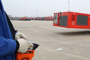
2.15 Coupling Function
Coupling transporters and remote control for coupling transporter can also be added. Many shipyard transporters can be used by transverse or longitude connection.
After connection, the function of many shipyard transporters is same as that of a single transporter.
Therefore, the transporter can be controlled by one man in any of the cabins since the communication is linked by connection cable hence making the operation is very easy.
2.16 Typical Tyre Replacement Process
During a tyre replacement process for instance, you will have to lift down the bogie with the tyres in need of replacement. After that, shut off the ball valve of the hydraulic suspension cylinder.
Lift the entire vehicle up and then make the replacement. After the replacement, lift the shipyard transporter down to the lowest level and remove the locking pin.
Open the ball valve and then lift the transporter to the desired driving level. Remember that each wheel bogie model has its unique rim.
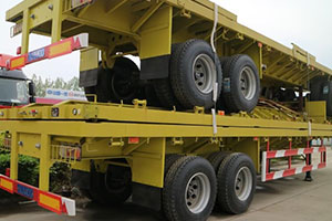
3. Different Shipyard Transporter Bogies
The hydraulic suspension is a very key set up for the shipyard transporter.
As the hydraulic system gets adjusted, the support system can create 3-4 support points needed to attain balance in the shipyard transporter via an equal distribution of the load on each of the tyres.
This is what makes the shipyard transporter a safe and reliable means of transportation for heavy loads especially in a rugged terrain.
Based on these hydraulic suspensions, shipyard transporters can be categorized into the following models:
- Wheel Bogies with Brake
- Wheel Bogies Without Brake
- Wheel Bogies with Drive
Different Models for Shipyard Transporters
The motor and the reducer installed on the wheel bogies with drive are used for providing the driving force required for the transporter.
Wheel bogies with brakes have an attached brake cylinder on it used for actualizing the service brake and the parking brake for the transporter.
These different models of shipyard transporter wheel bogies come with mechanical stoppers used for limiting the maximum position and use the minimum suspension cylinder stroke to manage the lowest position usually needed during transportation,
tyre replacement and wheel axle repair.
Each of these suspension cylinders are installed with bi-directional anti-break valve used for cover up in the event of pipeline breakage.
The increased flow will instantly trigger a differential pressure between the outlet and inlet port to block the pipeline. This will prevent the cargo from inclining to one side during such an eventuality.
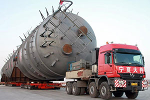
The shipyard transporter is a vehicle that has found major application in the lifting, loading and movement of ship sections and completely assembled ships to their docking areas.
They are suitable haulers for handling weight that is over 80 tons.
Despite its name “Shipyard Transporter”, this hauler can be used in many other areas where forklifts, cranes and hoist systems have not been able to handle bulky, weighty and long cargo.
A shipyard transporter will be needed when heavy equipment or sections need movement outdoors. Most of the in-built systems and apparatus of a shipyard transporter are controlled hydraulically.
The hydraulically suspension in each of the wheels are operated independently, a feature that enhances the maneuverability of the transporter.