Material Handling Transporter Ultimate Guide - Steel, Coil, Segments Transporter
Resources | by
The material handling transporter is also known as self-propelled platform transporter or simply an industrial transporter which is used for material handling and transportation of segments. It has the following functions:
Hydraulic lifting, driving, whole vehicle synchronous lifting, and multi-mode steering and multi transporter cooperative work.
One: What is an industrial transporter used for?
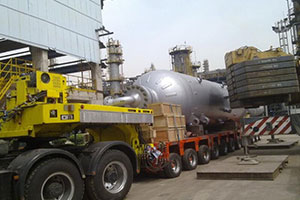
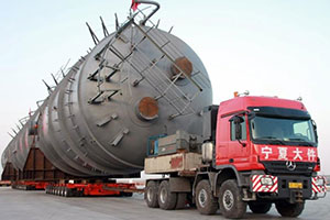
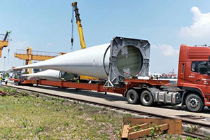
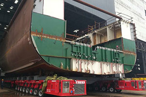
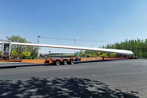
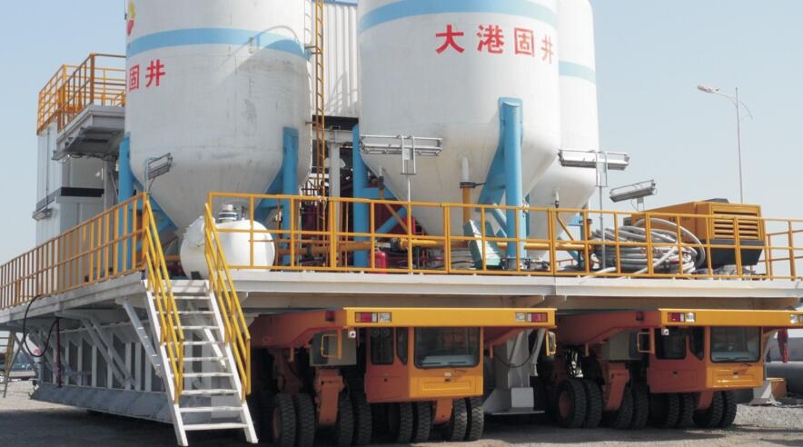
The self-propelled platform hydraulic transporter is adapted for use in the shipbuilding industry, in metallurgy fields, bridge construction and oil industry among other sectors.
In all these sectors, the primary use of a self-propelled platform hydraulic transporter is in material handling and for transportation of segments.
The axial loading in one line is subdivided into 32, 48, 64 and 76 tons. The system of steering for a self-propelled platform hydraulic transporter is a multi-mode independent configuration.
The single transporter load ranges from 35 to 1000 tons. With the selection of the coupling mode functionality, this transporter can do multi transporter cooperative work where the capacity may go up to as high as thousands of tons for the load.
Get Detailed Specifications!
Two: Different Models of the Material Handling Transporter
Here are the two different models of the material handling transporter:
2.1 Lightweight capacity transporter
The lightweight transporter has a loading capacity of between 5 and 100 tons. The axles are lighter compared to other models in the industry.
To function as desired, its total deadweight ranges from 18 to 23 tons. The loading per wheel bogie is 17 tons.
These among other specifications listed below make the lightweight capacity transporter suitable for handling certain loads as deemed fit for this type of transporter.
| Item | Parameter |
| Payload | Optional up to 100 tons |
| Dead Weight | 18,000kg-23,000kg |
| Load per Wheel Bogie | 17,000kg |
| Single Unit: velocity: Flat Road Without Load / Flat Road With Full Load | 0-12 km/h
0-6 km/h |
| Climbing Slope Ability with full load | Vertical Slope at 6%
Cross Slope at 2% |
| Wheel steering | Multi-way steering with PLC control |
| Fixed cabin type hanging beneath the platform | Yes |
| Platform height without load | 1450mm |
| Platform Lifting Distance | 0-600mm |
| Steering Radius | R=0 |
| Distance away from Ground while Driving | ≥150mm |
| Platform Size | Optional |
| Prime mover of hydraulic power pack | CUMMINS |
2.2 Heavy-duty hydraulic transporter
The heavy-duty hydraulic transporter can take loads starting from 35 tons all the way up to 1000 tons.

This type of a self-propelled platform hydraulic transporter is adapted to function for heavyweight applications due to a number of specifications relating its absolute dead weight, the number of axles per wheel bogies and so on.
Here are some of the specifications that distinguish a lightweight self-propelled platform hydraulic transporter from a heavyweight self-propelled platform hydraulic transporter.
Table 2 Heavy-duty Capacity Transporter Specs
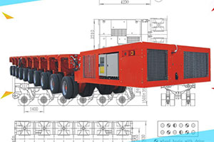
Three. Basics of the Material Handling Transporter
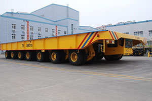
Its design is suitably made for the transportation of heavy loads, especially in the shipyard industry.
This special type of a transporter is made of a wheel bogie with a drive, platform frame, and wheel bogie with brake, hydraulic driving system, brake system,
power pack, hydraulic steering system, vehicle electrical system and an additional micro-electric system, a hydraulic lifting system, cabs.
Here are the different parts and sections in details:
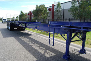
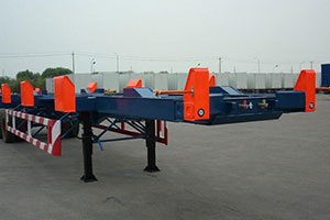
3.1 Frame Structure and Platform Cover
The frame is of a highly rigid construction meant to withstand bending forces. It also offers good flexibility when under torque. The entire vehicle is robust and sufficiently rigid to take up uniform loading.
Where steel has been used on the structural frame, load distribution signs and caution signs are put in place. The steel structure body of the transporter has lifting eyes used during the hoisting process.
The frame also comes with steel cover plates on the lift platform that can be disassembled when the need arises. The steel cover thickness is at least 5mm.
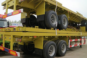
3.2 The Wheel bogie
The wheel bogie comprises a bogie frame, rocker arm, slewing ring, pendulum axle with brake or with drive and suspension cylinder and so on.
The suspension system is perfectly mounted on the slewing ring. On an uneven road surface for a transverse direction, the axle has an ability to swing to provide compensation for that situation.
When the transporter is on an uneven road surface of vertical sense, the hydraulic lifting cylinder set provides longitudinal compensation to keep the vehicle in balance.
As it goes down the slope, the platform keeps balance through adjustments made on the suspension cylinder.
3.3 Tires
The tires size of the material handling transporter is between 12 and 20 inches. To replace the tyres, you should lower the vehicle platform to lowest height and close up the shut-off valves on that specific bogie.
Insert a chain on the bogie frame and the rocker arm. The chain should easily fix these two parts because of the lifting eyes made on them.
After that, lift the platform to a point where the wheel is not touching the ground. Make sure that the wheel is hanging. It will be easy to make a tyre replacement while in that position.
You don’t need a jack or any other equipment in the process of doing so.
3.4 The Hydraulic Driving System
This transporter is equipped with a static hydraulic driving system that ensures a smooth run and acceleration of the entire vehicle.
Most importantly, it can generate the needed vehicle power matching the output power of the installed engine in various operating conditions.
Additionally, it can also prevent chances of the engine turning off normally caused by an overload on the driving parts and the engine at large.
The diesel engine speed and the vehicle transporter is under the control of a pedal accelerator.
3.5 The Hydraulic Steering System
On matters to do with steering, the vehicle is installed with a hydraulic system that adopts an electric hydraulic multi-mode steering. Various steering modes can be adopted as follows:
- All-wheel steering along
- Front-wheel steering
- Diagonal steering along
- Diagonal steering cross
- Circle steering.
- All-wheel steering cross, and so on.
The different steering modes are illustrated below:
- All-wheel steering along: Here, all wheel bogie produce a motion where all axial center lines traverse a point O as shown above. It could be inside, outside or to one side of the transporter. The inside turning radius minimum is zero.
- Front-wheel steering: For this mode, the vehicle’s turning center lies on the last axle-line which is defined by the cab chosen by the driver. It could either be -90°~ or +90°.
- Diagonal steering along: In this mode, all wheel bogies angle is kept the same. The driver can select any angle between -90°~ and +90°.
- Diagonal Steering Cross: When doing a diagonal steering cross, all bogies turn to the 90°steering angle. Here, the functions are similar as in a slant drive mode.
- Circle Steering: Steering in this mode means that all the wheel bogies get to move on a somewhat fixed pre-programmed position. During this movement, the vehicle is forced to turn around its center.
- All-wheel Steering Cross: An all-wheel steering forces all bogies to align themselves to a single point on the longitudinal axle of the vehicle.
Steering is conducted by way of rotating steer wheel, which is connected to an encoder. Each of the wheel bogies has an angular transducer that sends the position signal to the system’s controller.
The controller works by comparing the real position with the set position.
After that, proportional valves get to control each of the steering cylinders connected to the separate wheel bogie via the steering arm.
Should there be a steering deviation of more than 6°, the instrument panel’s warning lamp inside the cab flickers and prompts for the locking of the steering wheel.
3.6 The Hydraulic Lifting System
The vehicle is also installed with an electric hydraulic lifting system. The absolute lifting stroke of this vehicle platform is 680mm.
Ideally, when the platform gets lifted to half the stroke, i.e. 340mm, the movement made is sufficient to make compensation for the axial load.
The suspension cylinder is installed directly at the steered wheel bogies with joint bearings equipped on either side of the suspension cylinder.
This prevents the cylinder from undergoing damage. Through the operation of the lifting button to achieve the synchronized lifting of the platform, single point lifting is attained.
Again, there are four manual hydraulic valves used for lowering the vehicle platform during an emergency case.
3.7 Hydraulic Oil Cooling System
The self-propelled platform hydraulic transporter has an independent hydraulic oil cooling system installed on it. The hydraulic fluid for cooling is normally sucked from the reservoir via an oil pump to the radiator.
After the radiation, the hydraulic oil gets back to the tank directly. This independent cooling system makes sure that the hydraulic system doesn’t over-heat following many hours of permitted operation.
3.8 The Braking system
This material handling transporter has a compressed air braking system. This includes a service brake and a parking brake.
The service brake is pneumatic in nature whereas the parking brake uses mechanical parking braking units and can be released manually.
For the Service brake, the compressed air contained in the gas reservoir gets into the diaphragm cylinder to effect the braking.
Parking brake for the transporter is actualized through the spring force making it work even when there is a breakdown of the pipeline.
It is very much reliable for parking brake and the service brake since the brake valve and the relay valve get applied in the braking system. Smoothing the braking effect is realized by exercising control of the pedals.
3.9 Electric Control System
The operating voltage of a shipyard transporter is 24V with double200 AH batteries for use by the cabs electric-monitor and control instruments that have some special functions other than the general monitoring and the operational function.
They are listed as follows:
- Alarm lamps: Helpful in the blocking of the hydraulic high-pressure filter, the hydraulic return filter, the hydraulic suction filter and for alerts on the hydraulic oil tank lowest level.
- Lighting equipment: These include the blinker, headlamp, side marker lights, back-up lamp, emergency warning lamp and the tail lamp.
Also, there are control boxes where all the components of control are contained.
The fundamental electric system components include a special controller designated for the engineering vehicle, the angular sensor, the LCD display, the pressure sensor and so on.
All these are used using the import manufacturer’s productions, the military company’s productions and the top brand of joint-venture company’s productions.
3.10 Surface Machining and Finish
Each of the steel structure surfaces is well treated using sandblasting to realize the SA2.5 grade. Again, the painting thickness matches the set national standards and regulations.
Ideally, the absolute painting thickness is more than 110μm. Most importantly, the paint is chosen from a well-known brand globally. The surface colour is mainly medium yellow of code RAL1003. The small part sections are usually galvanized.
3.11 Safety Devices
The shipyard transporter is also installed with safety devices as follows:
- Anti-Break Technique of Hydraulic Pipes
These are usually double pipelines anti-break valves used for protecting the hydraulic lifting system in the event that one of the pipelines of one of the hydraulic lifting suspensions is broken.
To enhance safety on such a case, the anti-break valves shut off the broken pipe’s passageway through the pressure drops of the instant large flow.
At the same time, another normal pipeline is still linking the cylinder of the lifting suspension with that of the lifting suspensions in one supporting group.
For that reason, the transport will maintain the axial compensation function and carry on with the task at hand.
- The Overload Protection Device
The hydraulic steering and lifting system have independent overflow valves that make sure that the system pressure is not overloading.
This also ensures that the steering cylinder, the wheel bogies, the suspension cylinders and the steering structure are protected.
The 4 point lifting system has an equipment with four pressure sensors normally used in the monitoring of the platform payload.
The buzzer will send an alarm should the platform get overloaded or should it experience an unbalanced loading.
Most importantly, the transporter will not drive under such a condition as would realize an overload of 10% of the rated payload on the lifting system.
- Emergency Lowering Device
The shipyard transporter is installed with emergency lowering valves located under the frame platform. These are used for lowering the platform in an emergency situation that would warrant their use.
- Emergency Stop Function
Emergency stop switches are also installed in each of the cabs right under the four corners of this shipyard vehicle. These will successfully stop the transporter in an emergency situation as well.
- Remote Diagnosis Function
To further enhance safety, the remote diagnosis function, though optional is also available for sending useful data and information via the internet for appropriate action.
3.12 Coupling Function
The shipyard vehicle is also adapted for coupling with a similar transporter to enhance the transportation capabilities.
The coupling can be done side-by-side, end-by-end and at the same time realize the steering modes taking into account all-wheel steering along, diagonal steering along, front-wheel steering, diagonal steering across and circle steering mode and so on.
The entire transporter can be operated from any of the cabs. The electronic communication between the vehicles is interconnected via the coupling cables that makes the operation a lot convenient and easy.
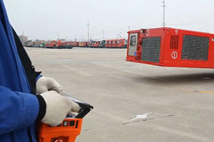
3.13 Remote Control Function
A radio remote control function is also available although optional. Following an authorization by the cab, the remote function will get started.
With the remote control system, the following functions can be achieved: emergency braking, stop, driving, lifting and multi-mode steering.
Get Detailed Specifications!
Conclusion
The self-propelled platform hydraulic vehicle that has found a lot of use. it has been used in many industries as the material handling needs would warrant its use in such settings.
The vehicle comes with useful components and built-in features that enhance its performance and use in material handling applications.
All components are parts are sourced and assembled from trusted brands around the globe.
Matters of safety are also factored in, giving the user comfort and assurance of staying safe in the process of lifting, loading and transporting materials on this rigid frame platform.